683RLoader
- Mechanical Self-Levelling (MSL)
- Unobstructed view
- Safe, easy mounting
- Effortless locking
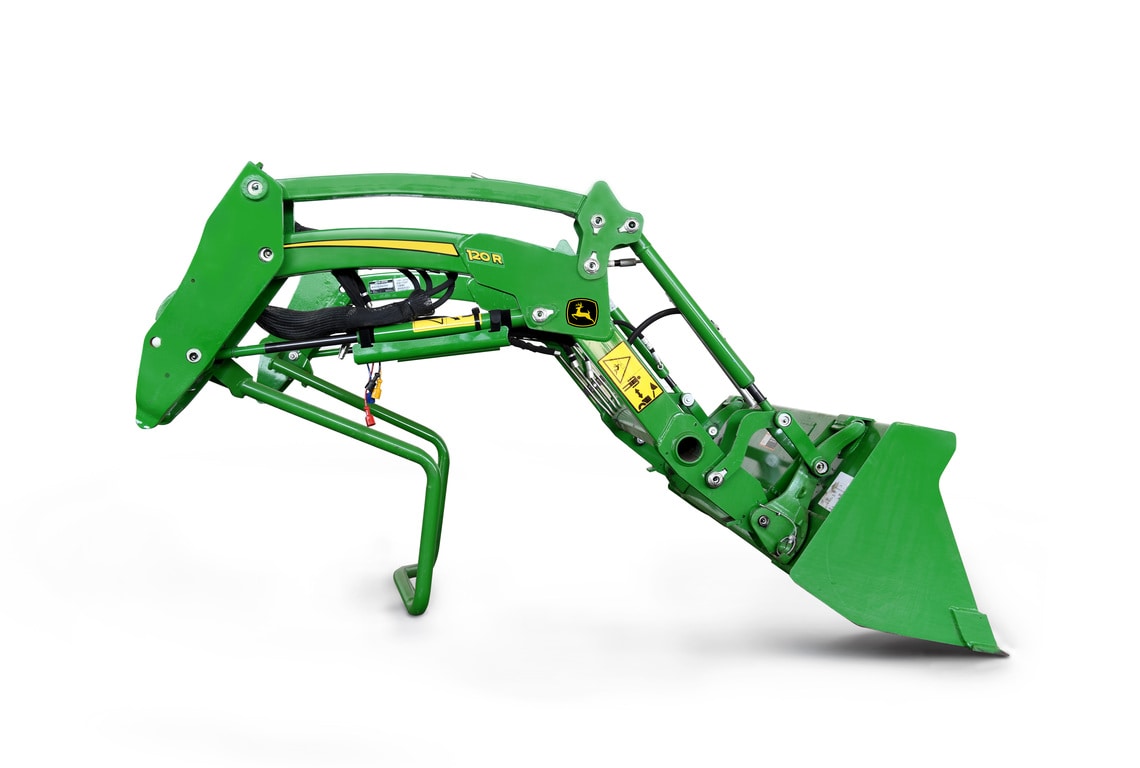
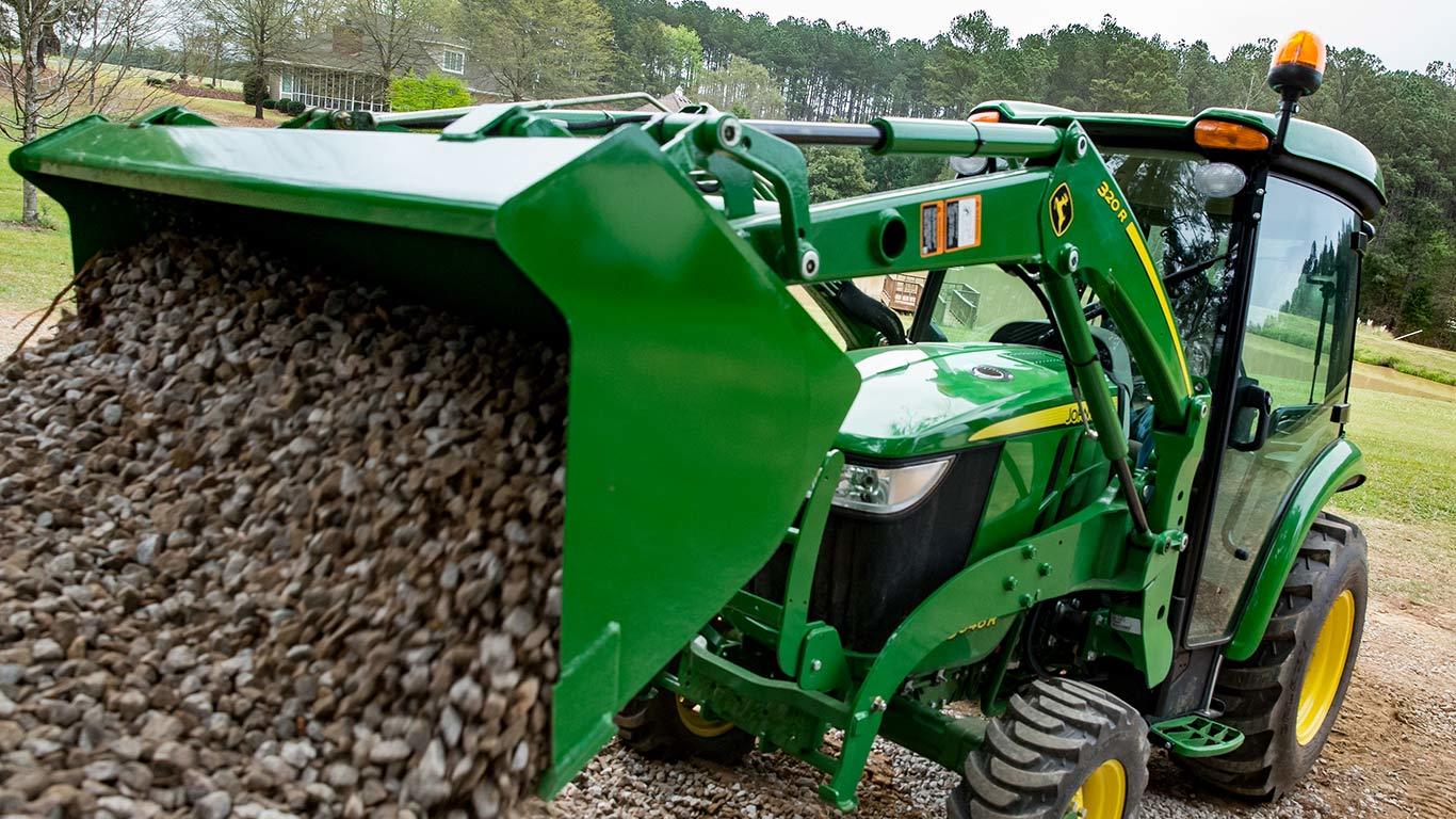
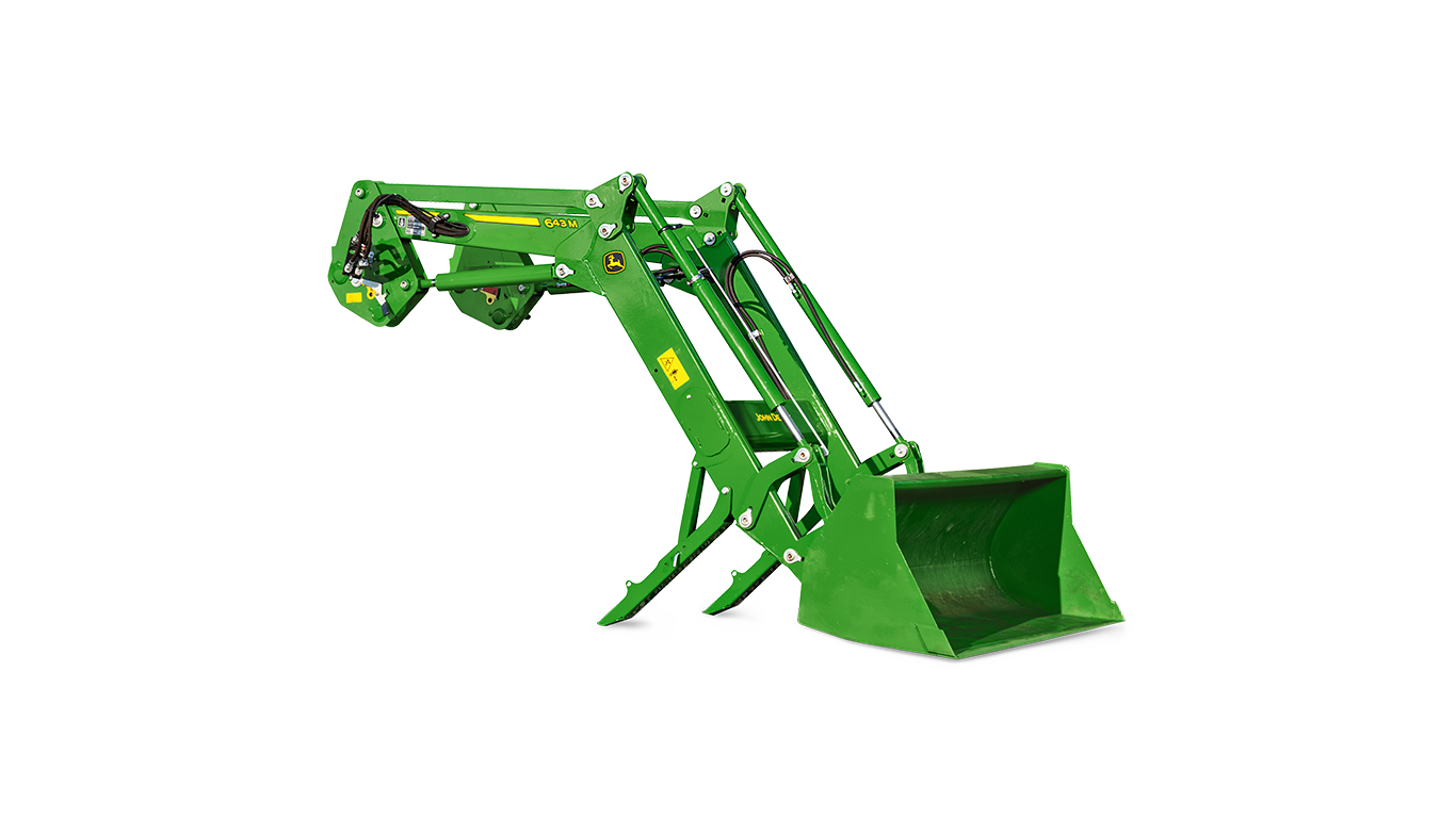
The new R‑Series Loaders are designed to work seamlessly with the latest 6R MY27+ Tractors, featuring a modern, functional design aligned with the new 6R Tractors styling for an optimal fit and a premium appearance. The new boom design places welds on the underside, leaving the top surface smooth to protect against moisture. The rounded top edges eliminate sharp corners, improving paint adhesion and providing a smooth, high‑quality finish. Together, these design and fit‑and‑finish enhancements ensure long‑lasting durability and help the loader maintain its appearance and performance throughout its working life, even at end of life.
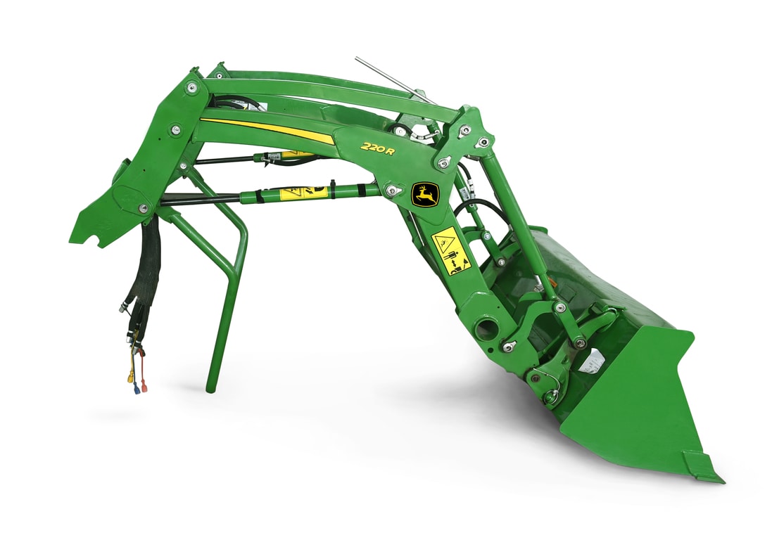
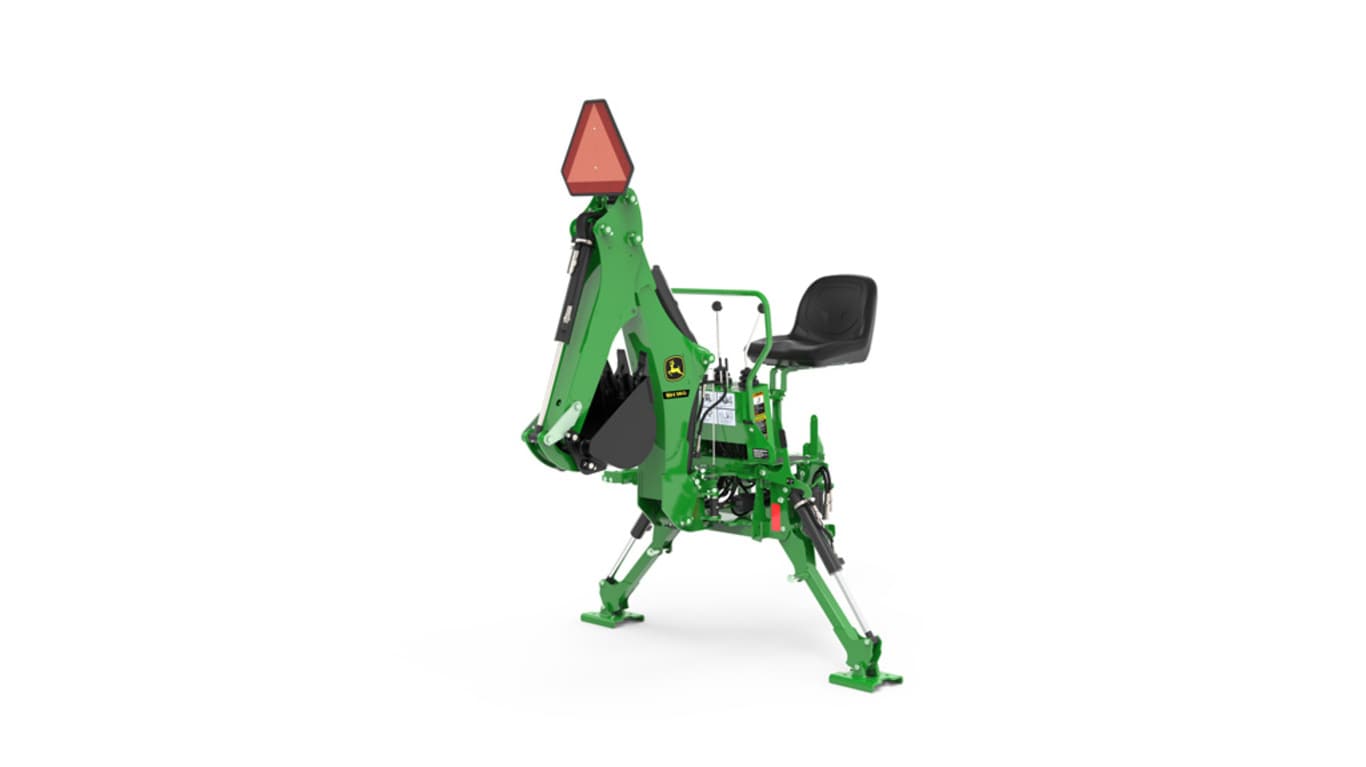
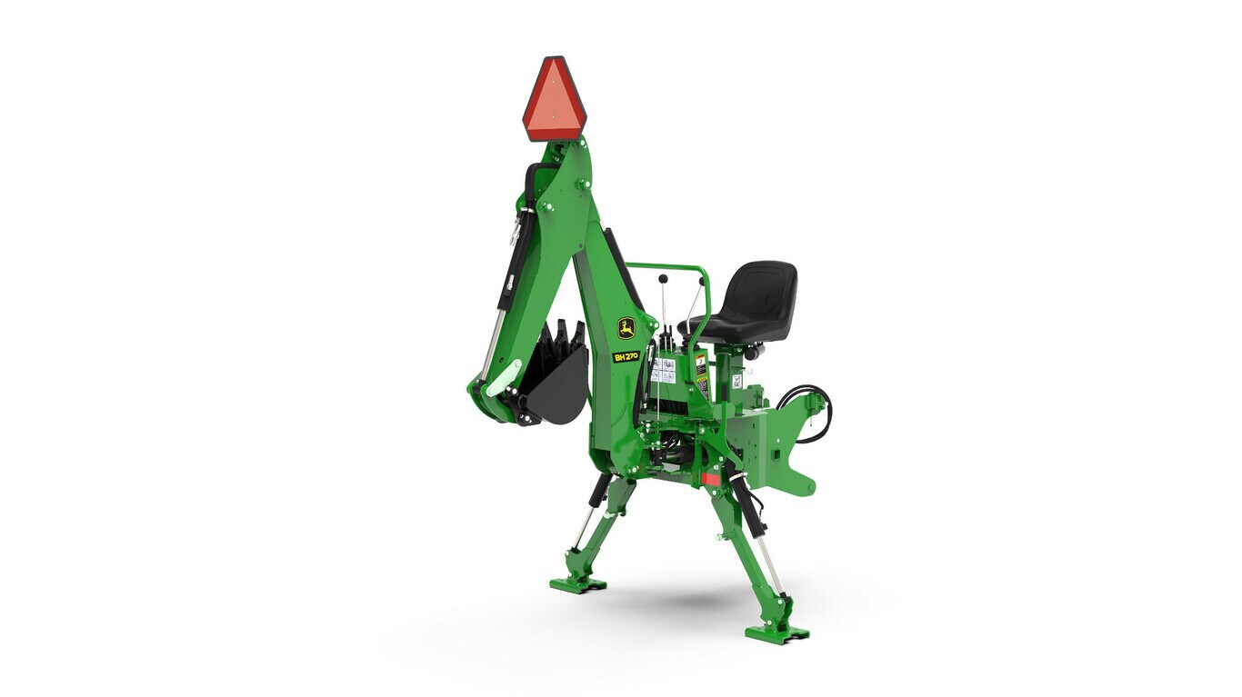
 685R Mechanical Self Leveling Loader
 Smooth, Weld Free Boom Top
Improved hydraulic routing maximizes visibility from the operator’s seat, creating a cleaner sightline when operating or attaching implements. A newly designed mast features an inner‑side cut‑out that provides a direct view of the loader latching pins. From the seat, operators can clearly see the latching points and confirm proper engagement during attachment. The result is faster, more intuitive coupling, increased confidence, and a simplified loader latching process.
The hose exit has been relocated to the inner side of the boom, providing cleaner routing, resulting in better visibility from the operator’s seat. Relief valve and bucket cylinder hoses connections have been relocated to provide a cleaner and less cluttered view around the loader. The depth of the hose clamp has been increased to allow greater hose flexibility and reduce stress during operation. Edge protections have been added to prevent contact with sharp edges, reducing the risk of hydraulic hose damage and improving durability.
 Improved hose routing
 Inner side hose exit
 Rear view
 Bucket cylinder hoses
The new mast design includes a cut out on the inner side, which provides clear visibility of the loader latching pins, allowing operators to clearly see the latching points directly from the seat when attaching the loader to the tractor. This enhanced visibility makes it easier to confirm proper engagement of the loader, improving confidence and simplifying the loader latching process.
 Right hand side Mast with cut-out
 Left hand side Mast with cut-out Zoom-in Right hand side
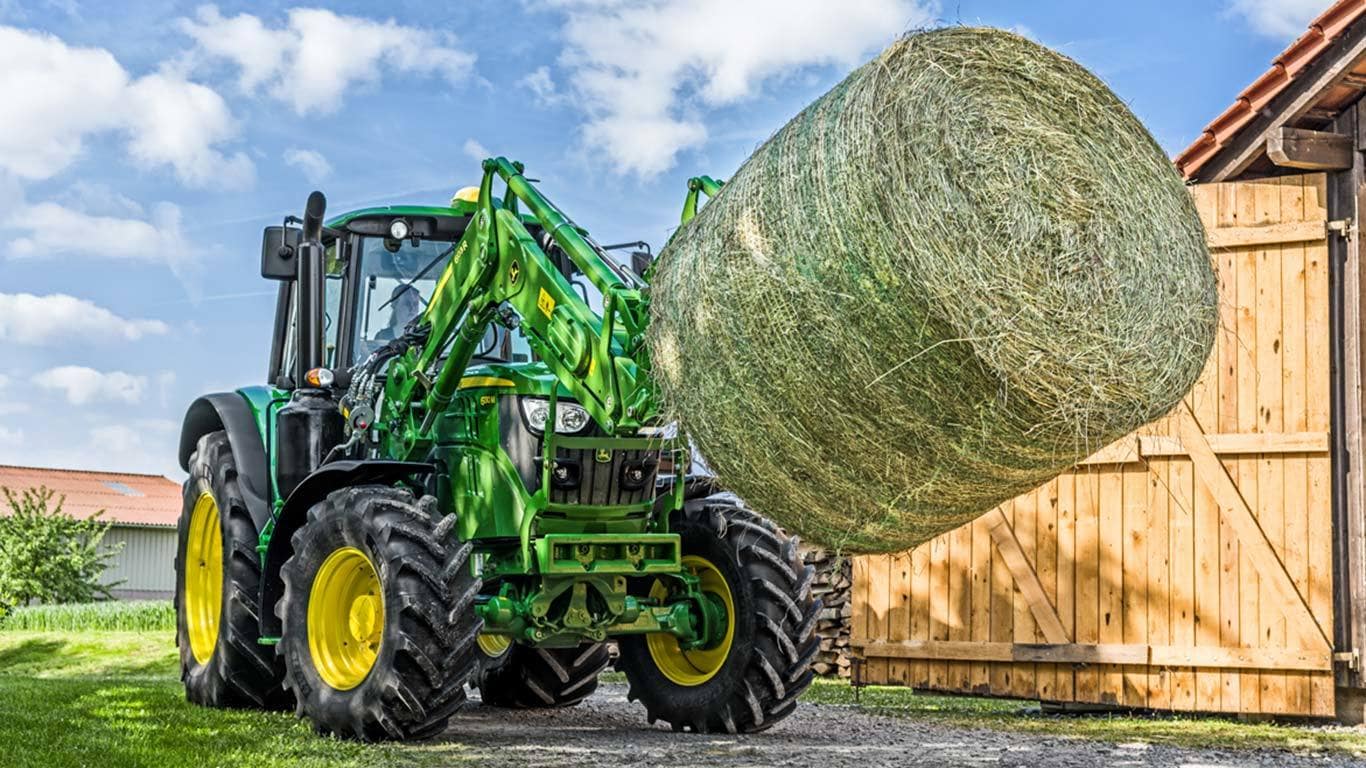
The R Series Loaders are equipped with a robust, easy to use bucket level indicator designed to help the operator in determining the bucket or attachment level position. Mounted on the righthand bucket cylinder, the indicator allows operators to quickly determine attachment level from the seat. It features two preset positions, one to indicate when the bucket is ground level and another to indicate when a bale handler, bale spear or pallet fork are ground level, plus a third adjustable position for additional attachments.
The indicator requires no tools for adjustment, and provides clear, reliable guidance to help operators work faster, more accurately, while preventing bucket damage, avoiding scratching concrete or soil surfaces, and reducing the risk of damage to pallets and bales caused by improperly leveled attachments.
 685R with Bucket level indicator
 Two preset indicators
Note: When equipped with the Technology Package, an electronic bucket level indicator replaces the standard indicator.
To further enhance visibility, R Series Loaders offer a high definition digital camera with two mounting positions, giving operators the flexibility to choose the best viewing angle for different operations. The camera is easy to adjust and reposition without tools, based on operator needs, delivering a clear, high quality image to support precise loader operation in a wide range of conditions.
The loader camera provides clear visibility of the loader carrier and surrounding area, including a convenient view of the carrier hooks for easier attachment connections. When using pallet forks, the camera also provides a clear view of the forks, making pallet handling more precise and effortless. The video feed is displayed directly on the Integrated G5in different and changing working conditions.
In bucket operations, the knee mounted loader camera provides enhanced visibility of the bucket and forward work area, empowering operators to handle material more accurately, work more efficiently, and reduce spillage.
 Two mounting positions available
 Knee-mounted camera
 Torque tube-mounted camera
Note: The system supports only one camera. Two cameras cannot be installed or operated
Code |
Name |
Description/Components |
8850 |
Vision Camera |
Vision Camera. Compatible only with 6R MY27+ Tractors. Includes camera mounted on torque tube and electric connection. Note: The system supports only one camera. Two cameras cannot be installed or operated. |
Operating in a dark barn, at duskor at night is part of everyday work. Loader‑mounted lights provide powerful illumination that improves visibility, allowing operators to work more comfortably and with greater confidence in low‑light conditions.
The LED lights are mounted directly on the loader boom, ensuring the light follows loader movement and illuminates the loading and unloading area precisely where it’s needed. This makes material handling easier and safer across variable working conditions.
For added convenience, loader lights are easily turned on/off via a soft key on the G5 Integrated Display either in the Loader App or convenience Display
 Loader lights mounted on the loader boom
 Loader and Tractor lights team up for strong night illumination
 Loader Lights activation via soft key in G5 integrated Display
 Convenience Display
Connect and disconnect the loader with less effort thanks to the ergonomically repositioned single point hydraulic connector.
An ergonomically positioned single‑point hydraulic connector with a straight handle enables easy loader hydraulic connection and disconnection, with a conveniently accessible storage bracket.
Hose lengths is optimized for natural alignment to allow the loader to connect easily without bending or twisting hoses.
The Multicoupler Loader Half is included factory installed when selecting code 1501 (Less Mounting frames). The Multicoupler Tractor/Loader halves are included when selecting option code 1503 (Mounting frames needed).
To disconnect the hydraulic connection between the loader and the tractor, it is necessary to release the hydraulic system oil pressure on the tractor.
Most hydraulic connections have been relocated within the torque tube, making it easier to identify potential leak points during inspections and service.
 Ergonomically positioned single point hydraulic connector
 Single point hydraulic connector with straight handle
 Easy to reach storage position for single point connector
The R Series Loaders includes in base an improved electrical connector with a new design and location that enhances reliability and long term performance. The loader’s electrical connection is separated from the hydraulic connection, reducing the risk of loose connections during operation and ensuring more stable performance in demanding conditions. This dedicated electrical interface is weather resistant and designed for durability, while also enabling future upgradability. A CAN based interface further simplifies the system by reducing wire count, improving communication efficiency, and contributing to lower overall tractor wiring complexity.
A more secure and weather resistant electrical connection means fewer interruptions, greater reliability in the field, and reduced downtime. Easier upgrades and simplified wiring help protect the customer’s investment, while improved connection stability provides confidence that the loader will perform consistently in all working conditions.
 Electrical connector on Loader side
 Electrical connection Tractor/Loader
Daily maintenance is simplified by consolidating 12 grease zerks into two conveniently located grease banks, allowing faster and more efficient servicing. Easily accessible service points reduce maintenance time and help promote consistent lubrication practices.
Protective caps are installed on the lowest carrier grease zerks to shield them from dust, manure, and debris, helping extend component life and reduce premature wear in demanding operating conditions.
 Central Greasing System

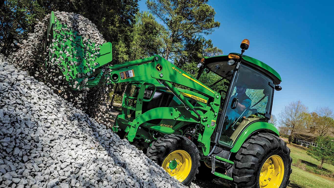
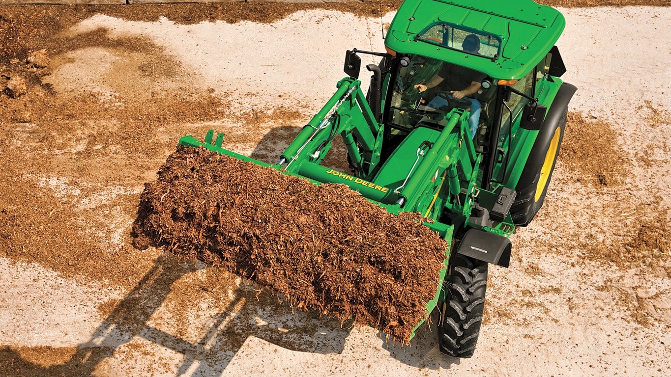
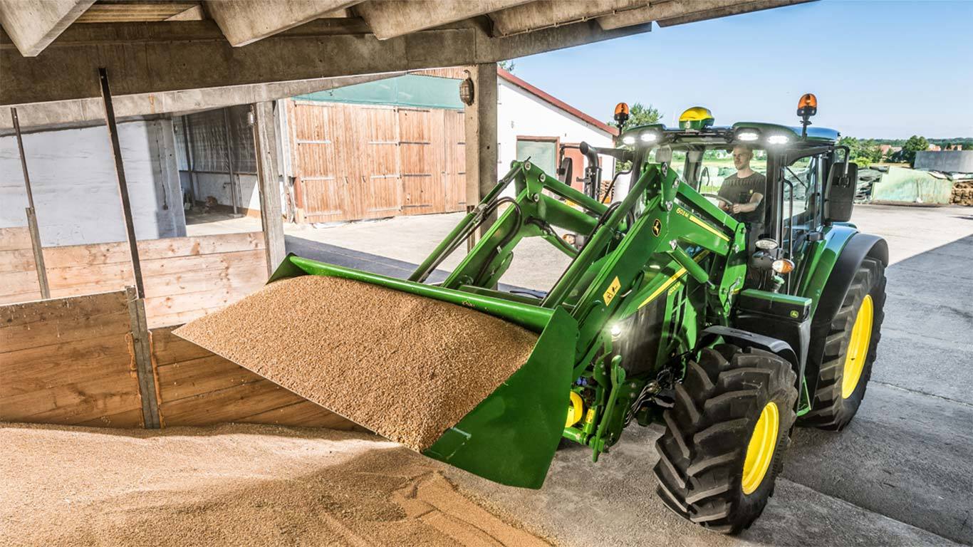
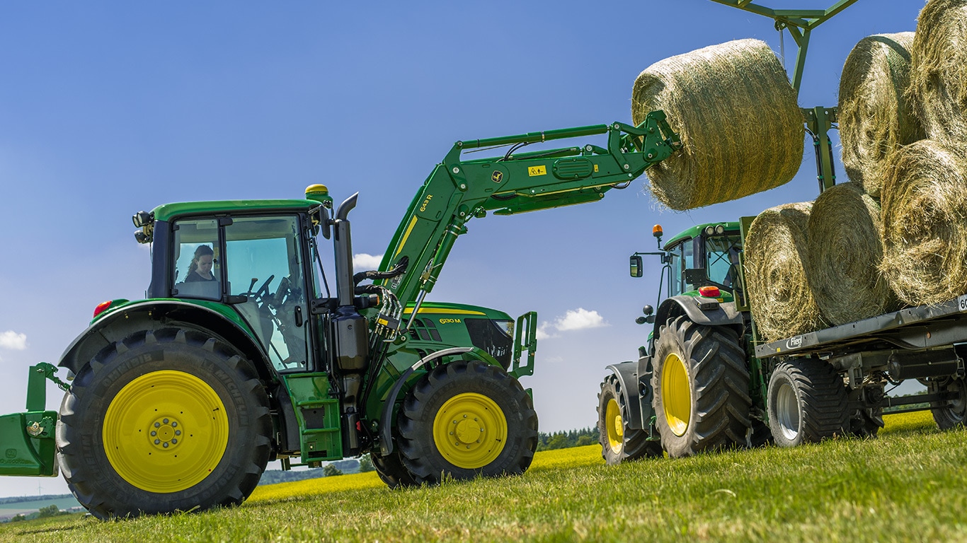
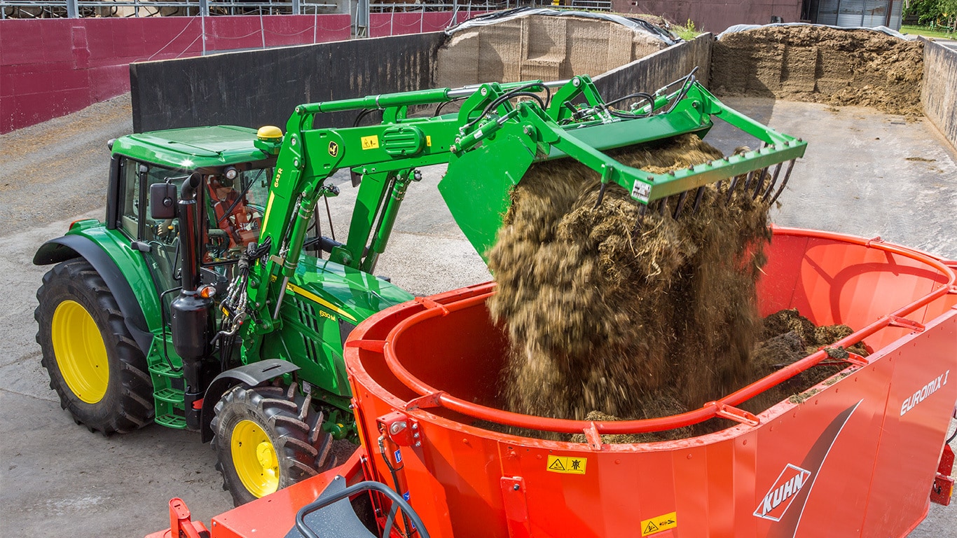
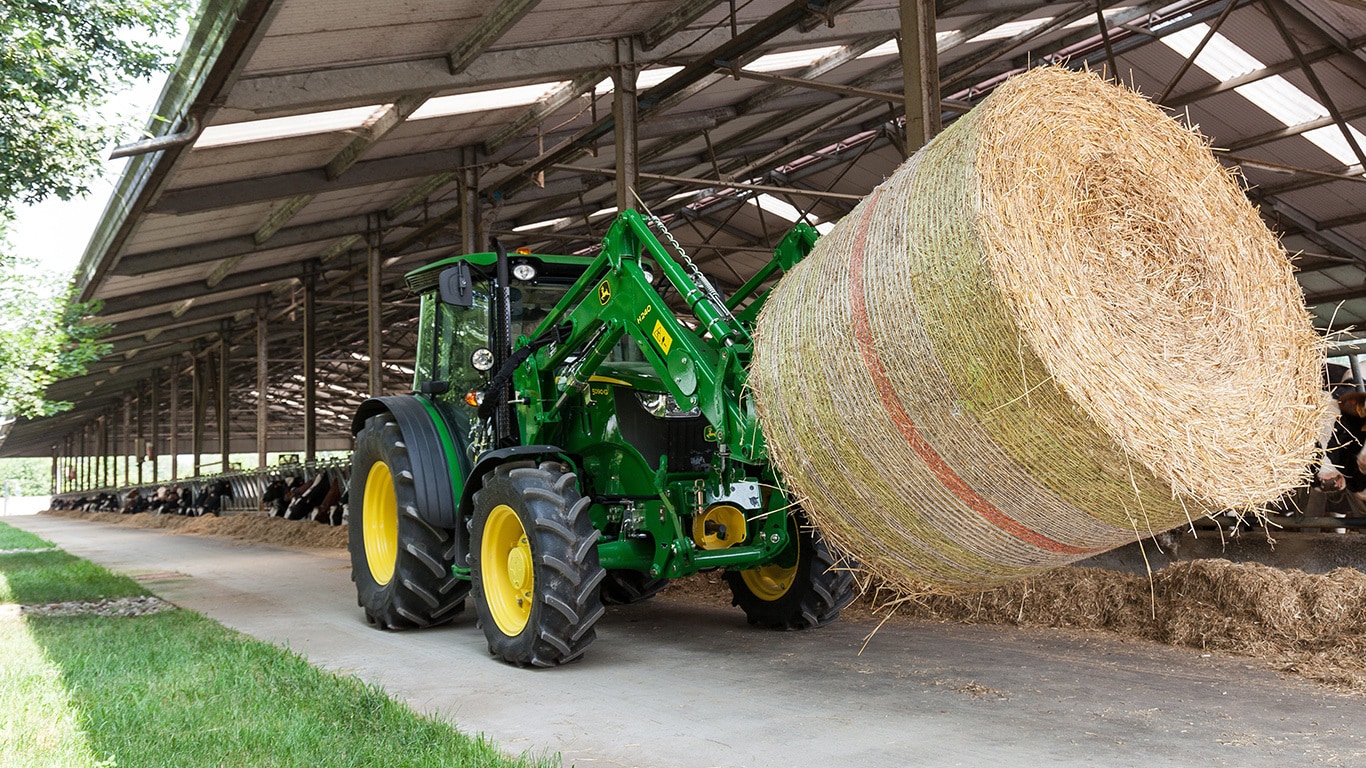
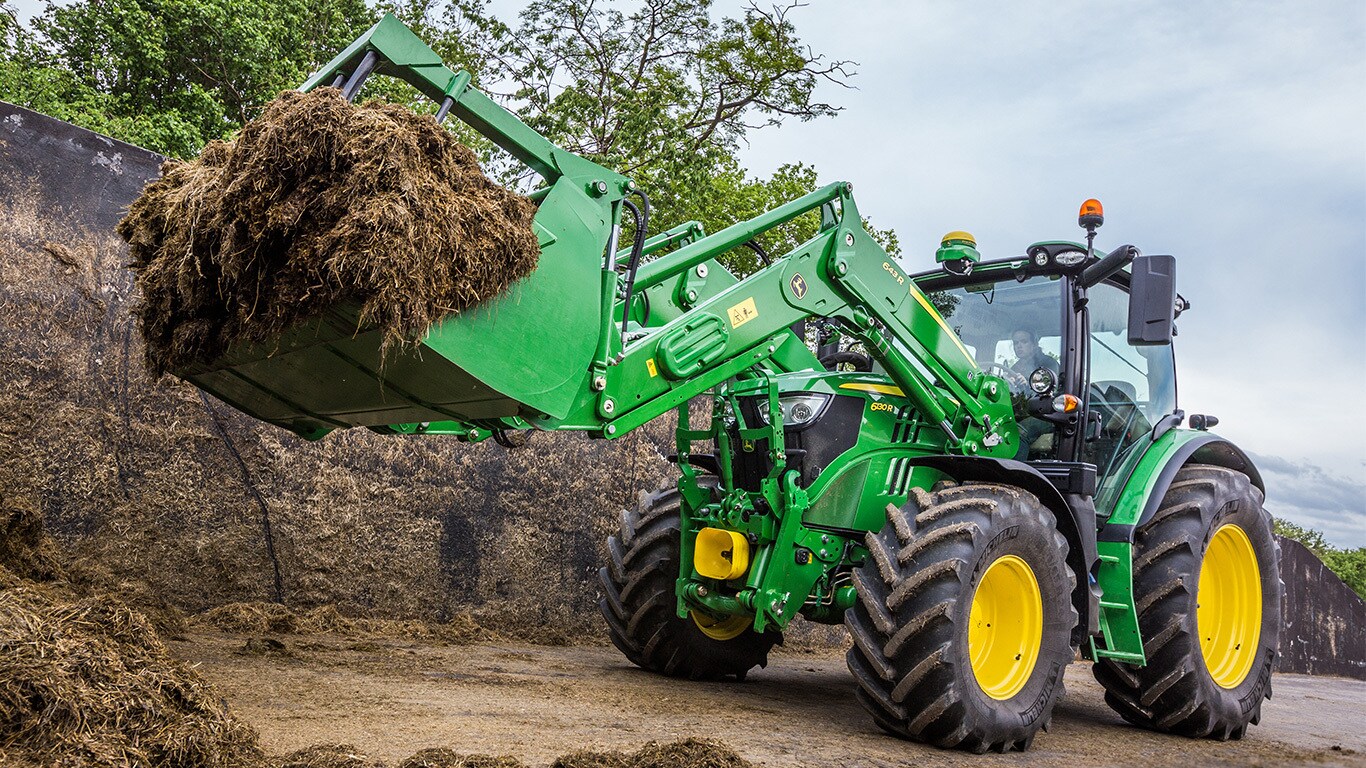
The new R‑Series Loaders deliver increased performance and productivity through improved leveling accuracy, a greater bucket rollback angle, and optimized bucket geometry. These enhancements allow the bucket to retain more material throughout the lift range, improving load control and overall efficiency. As a result, operators experience less material spillage—an important advantage when handling valuable commodities such as corn or grain.
By keeping more material in the bucket and reducing spillage, customers can move material more efficiently, protect valuable loads, and minimize product loss. This means faster cycle times, cleaner worksites, and more productivity from every load.
 Optimized bucket geometry with straight side plate
 Greater Rollback Angle
The new R Series Loaders for 6R MY27+ Tractors feature a significantly simplified electrical system designed to reduce complexity on the Tractor/Loader system. By minimizing connections and hardware, the system improves reliability while making installation and service easier.
All R Series Loaders come with a dedicated loader wiring harness and a 32‑bit controller in base, providing a strong foundation for future technology upgrades. This forward‑looking architecture allows new features to be added without major rework, protecting the customer’s investment over time.
All harnesses are optimally routed for durability, and key technology components are better protected. Pressure sensors are now installed at the torque tube and covered, improving robustness in demanding operating conditions.
One Harness, Multiple Capabilities
The main loader harness supports seamless integration of multiple options, including:
 Simplified Tractor/Loader electrical system
 Loader Main and secondary harnesses
The new R Series Loaders include an enhanced electrical connector in base, featuring a new design and improved mounting location to increase long‑term reliability. The loader’s electrical and hydraulic connections are now fully separated, reducing the risk of loose connections during operation and ensuring more stable performance in tough field conditions.
This dedicated electrical interface is weather‑resistant, highly durable, and designed for future upgradability. A CAN‑based interface further streamlines the system by reducing wire count, improving communication efficiency, and lowering overall tractor wiring complexity.
Together, these improvements deliver a cleaner, smarter, and more reliable electrical system—ensuring new R Series Loaders are ready for today’s work and tomorrow’s technology.
 Electrical connector – Loader side
 Electrical connector Tractor & Loader side
The Loader user interface has been optimized by consolidating three separate loader applications into a single, integrated Loader app. All loader features (when ordered) are now accessed from one location, giving operators faster, more direct access while reducing screen navigation, clicks, and setup time.
 Loader User Interface
It takes four steps to disconnect the loader: lower the loader, open the parking stand, remove the hydraulics, and unlock the mast pin.
 Loader placed on the ground with the bucket leveled (1)
 Open the parking stands (2)
 Unlock the hydraulic (3)
 Unlock the loader mast (4)
To disconnect the loader, the bucket has to be flat on a stable ground (1). The operator has to leave the cab and lower the self-adjustable parking stands on both sides of the loader (2): the self-adjustable parking stands allow the driver to park the loader on irregular terrain and still keep a good position relative to the mounting frame, to attach the loader correctly later on .The parking stands can be set without tools.
After lowering the parking stands, the hydraulic couplers on the right-hand side of the loader have to be removed (3) and the loader must be unlocked from the tractor mounting frames (4). After these four steps, the operator is ready to move the tractor (5 and 6).
 Leave the loader boom (5)
 Loader and tractor are disconnected (6)
 Store the parking stands (1)
 Connect the hydraulics (2)
Connecting the loader is fast and convenient thanks to the ramp design on the mounting frames and the automatic mast latch equipped with a floating device. Only drive the tractor to bring the mounting frames inside the mast until the latching indicators are in lock position. Then the driver can lift up the parking stands (1) and connect the couplers (2) for hydraulic and electric loader power to the tractor. Fast, intuitive and maintenance free design, the loader connection and disconnection brings the tractor ready for any tasks.
 Daily work: Connecting different implements
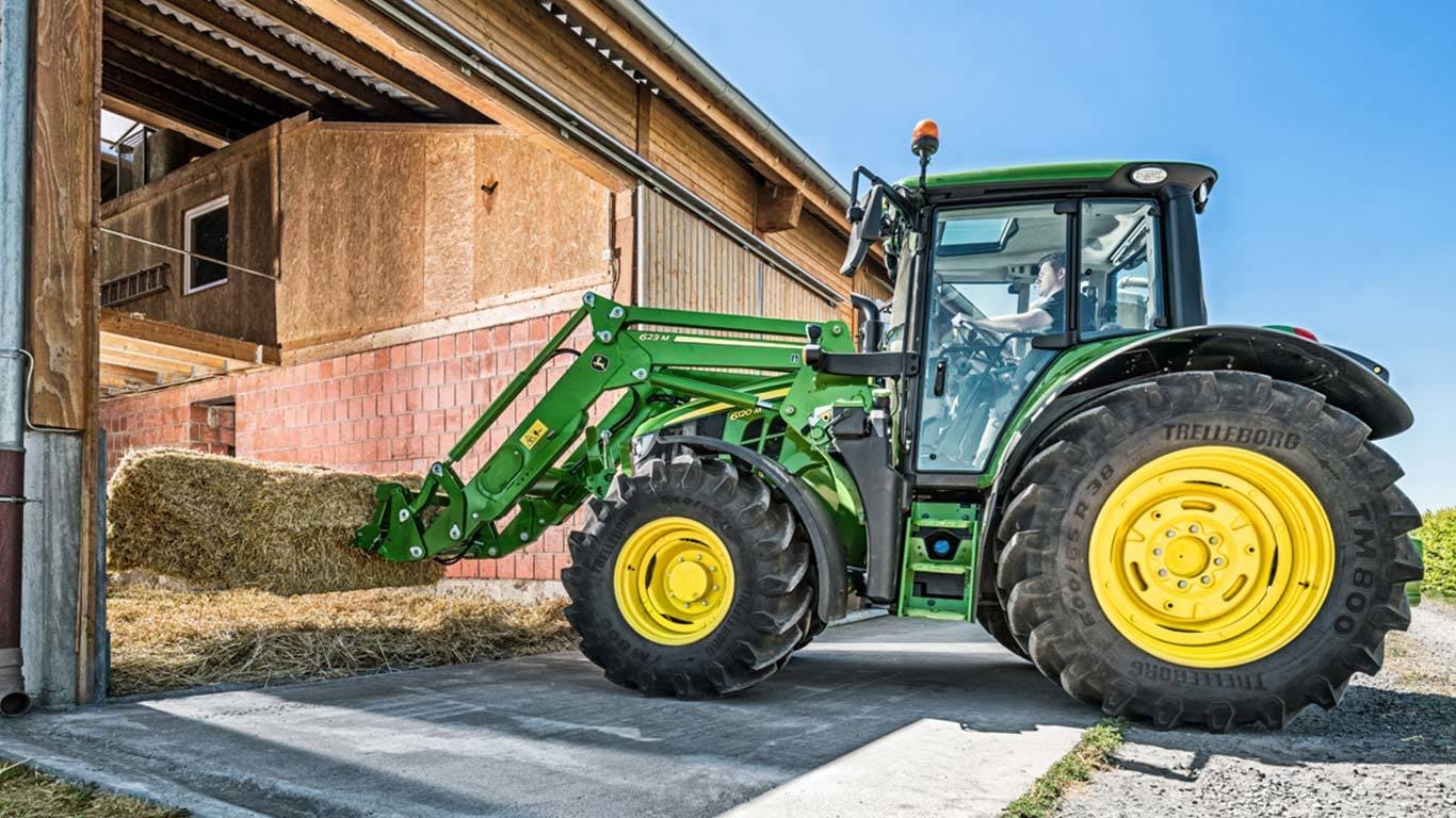
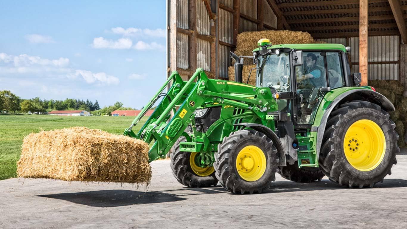
Changing the implements is a daily task for many front loader operators. Thanks to the patented automatic implement latch (AIL) the connection of various buckets, forks, or other implements can be done in less than 3 seconds. The dedicated treatment and material choice ensure the rod supports the heaviest applications, which provides a durable and lifetime solution. The AIL is a base feature of the Euro carrier, which is compatible with all Euro implements. It is also available with the Combi Euro MX carrier.
 Open the carrier handle (1)
 Remove the implement (2)
To unlock the implement, the operator has to open the handle manually (1). Optionally, this is possible to do from the cab with the hydraulic implement unlatching (HIU). It requires minimal effort to unlock the implement, without the need of tools. The convenient position of the handle allows easy access for the operator. The operator needs to pull the handle and turn it clockwise. The handle will stay in the required position.
The next step is to remove the implement from the carrier (2): tilt the implement and lower the loader until the bucket touches the ground. The carrier rod is released from the implement hooks. The carrier handle moves to a standby position allowing fast latching later on.
 Connect bucket with the carrier completely dumped
 Implement locking positions (1, 2) and the trigger of the AIL (2)
The Automatic Implement Latch (AIL) locks the implement as soon as the implement lug touches the trigger plate on the carrier (2). To achieve this, the top bar of the carrier has to be connected to the implement’s top hooks and after start rolling back the carrier. But there is no need to completely roll back the attachment. The implement is latched on both sides of the carrier (1, 2). The fast and easy locking performs regardless of loader height.
Automatic Implement Latch (AIL) in details:


Position of the carrier handle during the latching process
 John Deere R-Series Loaders are available with Mechanical self-leveling system (MSL)
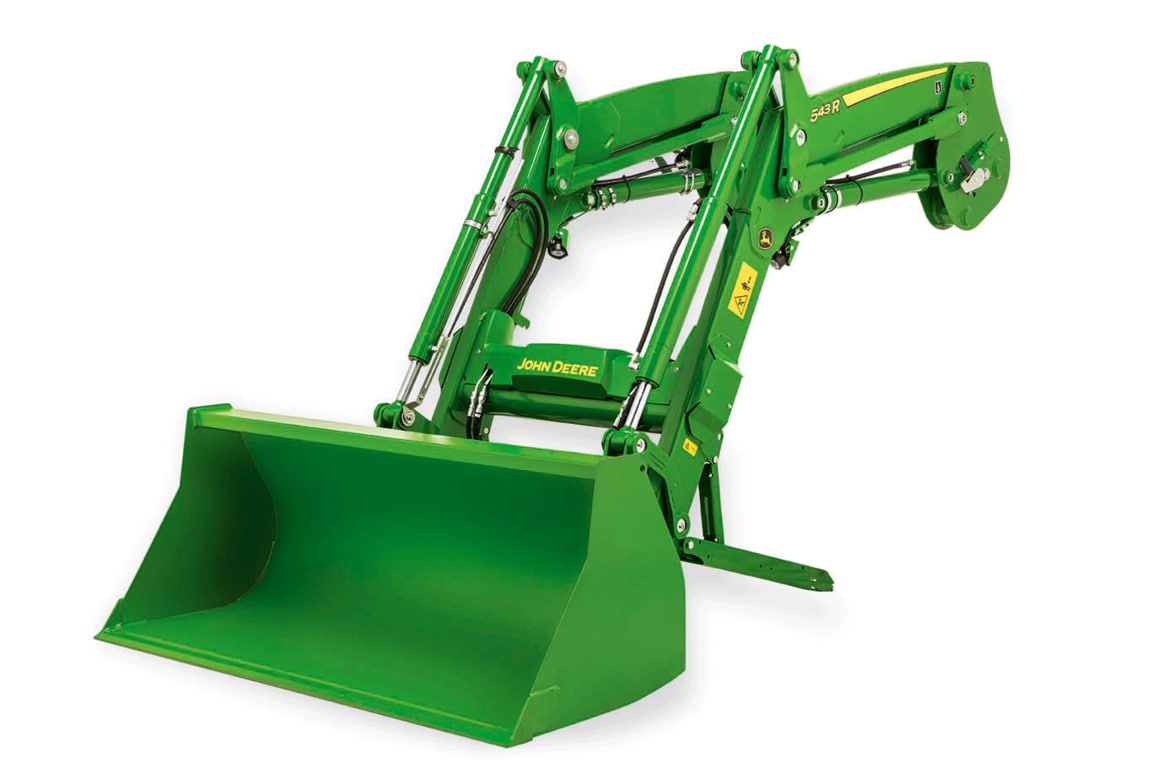
Due to the design and the loader kinematic, the R-Series Loaders feature outstanding power in regards to lift capacity and lift height. The power of the John Deere tractor is transferred to the loader via the hydraulic system.
The underslung levelling link of the mechanical self-loader (MSL) loader is connected to the false rod cylinders which results in fast cycle times (dumping and rolling back). The geometry allows a more rollback capacity which the operator can experience with stronger breakout forces. The compact boom design features lower pivot points, allowing easy and convenient access for greasing.
The detailed specification of the loaders can give an overview of the lift height and lift capacity of each loader (665R,685R).
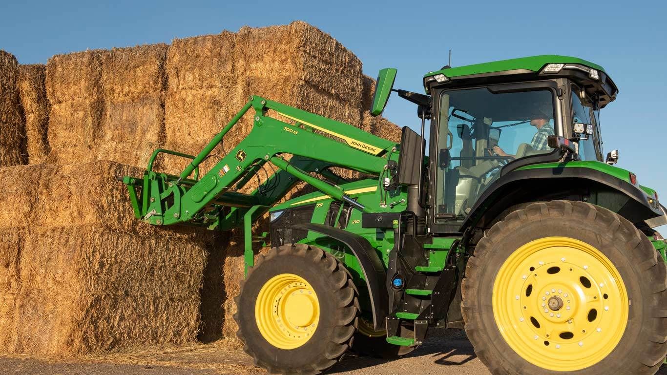
 John Deere R-Series Loaders are built with a high level of durability
 Durability supported by torque tube
The R-Series Loaders show a great level of durability due to the high-quality material. The modular cast-iron components on the loader are the foundation of a durable machine. The cast-iron mounting frames ensure a strong base for heavy-duty applications and guarantee a good connection to the tractor frame. This results in tested, reliable longevity.
The position and shape of the torque tube supports the heaviest loader applications and guarantees a stable behavior of the tractor and loader combination. Additionally, the compact boom design and the loader kinematics result in a strong and reliable solution the customer can experience in the field.
 Front loader on the test bench
 Cast-steel parts on the loader
To ensure a high quality with outstanding durability, the R-Series Loaders have been tested on a dedicated front loader test bench, where the loader is subjected to heavy duty farming operations. All pivot points are designed with a wider contact surface and are made from cast-steel material. The pivot pins has a dedicated diameter and undergo a specific treatment to ensure an outstanding durability.
The welded, directional bushings have a specific shape to provide ideal stress distribution and support the heavy-duty applications.
Major pivot points are equipped with replaceable bushings for low frequency of greasing, because the grease continuously is delivered during the loader work. New bushings can be installed thanks to the specific bushing design.
 Position of pivot points on the loader
 False rod cylinder
Fast bucket cycle times are important to dump the load from the bucket to be as productive as possible, while completing loading operations. The bucket cylinder design can have a major impact on the cycle time, especially for the mechanical self-levelling (MSL) loaders.
All MSL R-Series Loaders utilize false rod bucket cylinders. A false rod cylinder has a smaller displacement of oil requirement on the head end of the cylinder, which allows the cylinder to retract much faster than a normal cylinder.
 Shut-off valve open
 Shut-off valve closed
A hydraulic shut-off valve is included in base with the R-Series Ag Loaders to ensure the loader does not lower suddenly. This allows the boom to be locked if someone is required to be located under the loader boom, for example, during service work on the tractor.
| Specifications | ||||
|---|---|---|---|---|
| John Deere 683R Loader |
| Lift height | 4,500 mm (pivot) | |||
|---|---|---|---|---|
| Lift capacity | 2,538 kg (800 mm ahead of pivot) | |||
| Clearance | 3,480 mm (full height, bucket dumped) | |||
| Rollback force | 2,870 kg (ground level) |
Specs apply to MSL levelling for 6175R/6195R with front tyres 600/70R28 and rear tyres 650/85R38; actual specs may vary
Product features are based on published information at the time of publication. Product features are subject to change without notice. Contact your local John Deere dealer for more information.